Three LiDAR-inertial odometry algorithms from the same research lab. All of them run on consumer-grade hardware. All three are open-source. Yet they behave very differently once you strap them onto a handheld scanner and walk through a warehouse, a construction site, or a narrow hallway.
The difference isn't about which one is "best." It's about which one matches the motion patterns, sensor setup, and output requirements of your specific build. If you've already chosen a LiDAR sensor for your handheld scanner, the SLAM algorithm is the next decision — and it determines how accurate your point cloud actually ends up.
This comparison covers FAST-LIO2, R3LIVE, and Point-LIO from HKU-MARS lab, with practical configuration notes for the Livox M360 and a build recipe at the end. Each algorithm has its own section, then a direct comparison table, then a decision framework.
Why Handheld Scanning Breaks Generic SLAM
A ground robot moves in predictable ways: mostly 2D, relatively constant velocity, well-defined gravity vector. The SLAM algorithm can assume the IMU's gravity reference is stable and that angular rates stay within a narrow band.
A handheld scanner operator violates most of those assumptions. You walk, stop suddenly, crouch, rotate the device to scan a ceiling, wave it to fill in a corner, and occasionally bump into doorframes. The IMU sees angular rates that swing from near-zero to 75 rad/s in milliseconds. The LiDAR frame rate and the operator's ego-motion create a mismatch — by the time a single LiDAR scan is collected, the device may have moved several centimeters and rotated 5–10 degrees.
These three algorithms handle that problem differently, even though they share the same lineage at HKU-MARS.
FAST-LIO2: The Default Choice for Most Handheld Builds
FAST-LIO2 (Fast LiDAR-Inertial Odometry) is the most widely adopted LIO algorithm in the ROS ecosystem, with over 8,000 GitHub stars. It's probably what your colleagues use, what most tutorials reference, and what most researchers benchmark against.
How it works
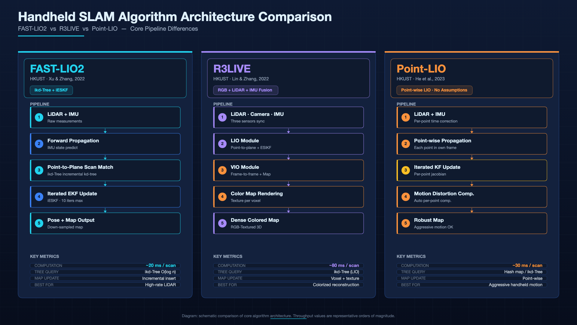
FAST-LIO2 uses tightly-coupled iterated extended Kalman filtering on a sliding window of states. The key innovation is direct scan-to-map registration: instead of extracting features (edges, planes, corners) from each LiDAR frame, it registers raw points directly against an incrementally built map using an ikd-Tree. This avoids the information loss that comes with feature extraction and works well with sparse, non-repetitive scanning patterns.
The iESKF (iterated ESKF) filter fuses LiDAR measurements with IMU pre-integration between frames. For each new LiDAR frame, it iteratively refines the state estimate — position, velocity, orientation, and sensor biases — by minimizing the point-to-map residuals. No feature extraction, no descriptor matching. Just raw points against a growing map.
Benchmark performance
Across 19 benchmark sequences from public datasets (including HILTI, Newer College, and S3E), FAST-LIO2 consistently achieves higher accuracy at lower computational cost than competing LIO systems. On an NVIDIA TX2, it processes 100,000+ points per frame at frame rates exceeding 10 Hz — well above what the Livox M360 delivers at its default integration settings.
The practical implication for handheld scanning: FAST-LIO2 will not be your bottleneck. Your bottleneck will be LiDAR point rate, data transmission bandwidth over Ethernet, and disk I/O for recording rosbags.
M360 configuration specifics
Setting up FAST-LIO2 with the Livox M360 is straightforward. The Livox ROS driver outputs data in CustomMsg format (per-point timestamps), which FAST-LIO2 accepts natively.
The critical parameter is the relationship between cut_frame_num and orig_odom_freq:
cut_frame_num * orig_odom_freq = 50If your LiDAR publishes at 10 Hz, set cut_frame_num to 5. If at 20 Hz, set it to ~2.5 (round to 3). This ensures the algorithm accumulates enough points per processing cycle for reliable registration without adding excessive latency.
Default FAST-LIO2 parameters work for most handheld scenarios out of the box. You only need to tune if you're doing something unusual — very fast scanning (running with the device), extremely feature-poor environments (long corridors with no furniture), or outdoor ranges beyond 25m.
Strengths
- Runs on ARM platforms — NVIDIA Jetson, Raspberry Pi 4B, Khadas VIM3. A Jetson Orin Nano at 40 TOPS is overkill; FAST-LIO2 uses maybe 15–20% of one compute core.
- Minimal parameter tuning for standard environments. Most users never touch anything beyond the cut_frame_num relationship.
- Direct scan-to-map means it works with any LiDAR that provides per-point timestamps, regardless of the scanning pattern. The M360's non-repetitive pattern is handled without special configuration.
Weaknesses
- No loop closure. If you walk a large building and return to the starting point, accumulated drift stays in the map. For small-to-medium scans (rooms, apartments, single warehouses), this drift is usually acceptable. For building-scale or campus-scale scans, it becomes a real problem unless you post-process with tools like SC-LIO-SAM or external loop closure modules.
- Fails in LiDAR-degraded environments: long featureless corridors, glass walls, open fields. When the LiDAR stops providing usable geometric constraints, the IMU dead-reckons and drift accumulates rapidly.
- No RGB output. You get a geometric point cloud with no color information. If you need colored maps for client deliverables, you'll need a separate photogrammetry pipeline.
R3LIVE: When You Need Colored Maps and Degradation Resilience
R3LIVE (Real-time 3D Reconstruction) extends FAST-LIO2 by adding a visual-inertial odometry subsystem that renders texture onto the 3D point cloud in real time. Published at ICRA 2022, it addresses two problems that FAST-LIO2 doesn't: color output and LiDAR degradation.
How it works
R3LIVE runs two tightly-coupled subsystems simultaneously:
- The LIO subsystem — essentially FAST-LIO2 — handles geometric odometry and map building.
- The VIO subsystem renders the map's texture by projecting camera frames onto the point cloud and refining the color values using photometric error minimization.
Both subsystems use direct methods. The VIO doesn't extract ORB features or track keypoints; it directly minimizes pixel-level reprojection error against the textured map. This gives R3LIVE an advantage in texture-poor scenes where feature-based visual odometry would fail.
When the LiDAR degrades — glass-walled offices, open fields, long hallways with repetitive geometry — the VIO subsystem compensates by providing visual constraints to the state estimator. When vision degrades — dark environments, visual texture-less walls — the LIO subsystem compensates. The dual-redundancy approach is what makes R3LIVE particularly interesting for handheld scanning, where operators frequently encounter mixed environments.
Benchmark: NTU-VIRAL results
On the NTU-VIRAL dataset (designed specifically for testing LiDAR-visual-inertial systems), R3LIVE++ achieves 0.185m RMSE, outperforming single-modality systems in sequences with deliberate LiDAR and vision degradation. On the M2DGR dataset, RMSE is 0.478m across 6 sequences.
These numbers need context. RMSE in SLAM benchmarks depends heavily on trajectory length and motion speed. For handheld scanning of a 50m room, 0.185m RMSE translates to a map that's accurate to within a couple centimeters for most surfaces — well within tolerance for facility management and construction documentation.
M360 + camera configuration
Adding R3LIVE to an M360 build means adding a camera and dealing with three calibration problems:
- Hardware synchronization — the camera shutter, LiDAR scan timing, and IMU sampling all need to be on a shared clock or timestamp-corrected. The M360 supports IEEE 1588-2008 PTP, which helps if your compute platform and camera also support it. For most DIY builds, software time synchronization via NTP or chrony is the practical approach.
- LiDAR-IMU extrinsic calibration — the rigid body transform from the IMU to the LiDAR origin. Use the LI-Init tool from the same HKU-MARS group. With the M360's built-in IMU, this calibration is straightforward since both sensors are in the same housing.
- Camera-LiDAR extrinsic calibration — the transform from the camera to the LiDAR. This is the tedious one. You'll need a calibration target (checkerboard or AprilTags), and you'll need to collect data in a feature-rich environment. The R3LIVE repository includes calibration tools, but expect to spend a few hours getting it right.
Calibration drift is the most common source of map error in R3LIVE builds. If your colored point cloud shows color bleeding between adjacent surfaces, recheck your camera-LiDAR extrinsic before blaming the algorithm.
Strengths
- Real-time RGB-colored point cloud. Walk through a room, and the resulting point cloud has texture mapped onto it. This is the main selling point for applications where stakeholders need to see more than raw geometry: construction documentation, interior design, facility handovers.
- Handles LiDAR-degraded environments better than FAST-LIO2 because the visual subsystem provides an independent motion constraint. Glass-walled offices and open outdoor areas become survivable.
Weaknesses
- Requires an additional camera. Hardware cost, power draw, and physical integration all increase. A typical camera for R3LIVE — something like an Intel RealSense D435i or a global-shutter USB camera — adds $100–300, 2–5W, and another cable to manage.
- Computational load is substantially higher. The VIO subsystem rendering texture in real time doubles or triples the compute requirement compared to FAST-LIO2 alone. A Jetson Orin Nano handles it, but you'll see 40–60% GPU utilization at steady state versus the ~15% that FAST-LIO2 alone demands.
- Setup complexity is significant. Three-sensor calibration, synchronization, and tuning multiple parameter files mean you'll spend days rather than hours getting a reliable build.
R3LIVE is not the right default choice. It's the right choice when you specifically need colored maps or when you know you'll be scanning environments where the LiDAR alone won't be enough.
Point-LIO: For Fast Motion and High-Rate Feedback
Point-LIO (point-level LiDAR-Inertial Odometry) takes a fundamentally different approach. Instead of processing LiDAR data in frames, it processes individual points as they arrive from the sensor.
How it works
Most LIO algorithms, including FAST-LIO2 and R3LIVE, accumulate LiDAR points into a "frame" (a batch covering some time window) and then register that frame against the map. Between frames, the IMU propagates the state estimate. The problem: if the device moves significantly during the accumulation window, points within the frame get motion distortion.
Point-LIO eliminates this by processing each point individually at its own timestamp. When a new point arrives, the algorithm:
- Propagates the IMU state estimate to the point's timestamp (microseconds of motion)
- Projects the point into the current map using the propagated state
- Updates the state estimate if the residual is significant
This produces odometry output at the LiDAR's native point rate — effectively 4–8 kHz with the M360 at 200kHz point rate. There's no frame-level motion distortion because each point is individually corrected.
Why point-level matters for handheld
Consider an operator scanning a narrow corridor at walking speed, rotating the scanner to capture ceiling detail. In the ~100ms that FAST-LIO2 accumulates a frame, the device moves roughly 10cm and rotates maybe 15 degrees. That's acceptable. Now consider an operator running down a hallway to capture a large space quickly, or a scanner mounted on a pole that vibrates. The intra-frame motion gets large enough that frame-level processing introduces measurable error.
Point-LIO's per-point processing handles this naturally. Each point is individually de-distorted and registered. The 4–8 kHz output frequency also provides near-instantaneous state estimates for any real-time feedback application — though most handheld scanning doesn't need that rate.
M360 configuration specifics
Point-LIO requires per-point timestamps from the Livox driver, which the standard Livox ROS driver provides in CustomMsg format. The key configuration differences from FAST-LIO2:
IMU saturation parameters — Point-LIO's resistance to vibration comes from correctly modeling IMU saturation. Set these based on the M360's built-in IMU specs:
satu_acc: 200  # m/s^2, from ICM40609 datasheet
satu_gyro: 35  # rad/s, from ICM40609 datasheet
Gravity norm — Point-LIO uses the accelerometer norm as a state observable:
acc_norm: 9.81Extrinsic estimation — if you know the M360's IMU-to-LiDAR transform (and you should, since they're in the same housing), set extrinsic_est_en: false and provide the values directly. Letting Point-LIO estimate them adds unnecessary variables.
IMU disable option — Point-LIO can run without IMU data at all (imu_en: false). This uses the LiDAR point constraints exclusively. It's slower and less accurate than with IMU, but it works. Not recommended for handheld scanning where the IMU provides the primary motion constraint, but useful as a debugging tool.
Strengths
- The most robust to IMU saturation and vibration of the three algorithms. Tested at angular rates up to 75 rad/s, Point-LIO maintains tracking where frame-based LIO systems diverge.
- No motion distortion in the output. Each point is individually corrected.
- Runs without IMU as a fallback — useful for debugging or for sensor configurations where IMU data is unreliable.
- Per-point processing naturally handles the M360's non-repetitive pattern without needing frame accumulation logic.
Weaknesses
- No RGB output, same as FAST-LIO2.
- No loop closure.
- 4–8 kHz odometry output is useful for control applications but overkill for most handheld scanning workflows. You're recording rosbags at this rate and downsampling later, which wastes storage and I/O bandwidth.
- Less community adoption than FAST-LIO2 — fewer tutorials, fewer troubleshooting resources, more time spent reading source code when something goes wrong.
Point-LIO is worth considering when your handheld scanner operates in conditions that break frame-based LIO: high vibration (pole-mounted scanning), rapid motion changes, or environments where the operator is moving erratically. For calm walking-speed scanning in feature-rich environments, FAST-LIO2 will give you the same or better results with lower overhead.
Side-by-Side Comparison
| Dimension | FAST-LIO2 | R3LIVE | Point-LIO |
|---|---|---|---|
| Sensor input | LiDAR + IMU | LiDAR + IMU + Camera | LiDAR + IMU (optional) |
| Map output | Geometric point cloud | RGB-colored point cloud | Geometric point cloud |
| Odometry frequency | ~10–20 Hz | ~10–20 Hz | 4–8 kHz |
| Loop closure | No | No | No |
| Feature extraction | None (direct method) | None (direct method) | None (point-level) |
| LiDAR degradation | Fails without external correction | VIO compensates | Point-level less susceptible |
| RGB support | No | Yes, real-time | No |
| Compute requirement | Low (ARM-capable) | High (camera + rendering) | Low-medium |
| IMU saturation handling | Standard iESKF | Standard (LIO side) | Explicit saturation modeling |
| Motion distortion | Frame-level correction | Frame-level (LIO side) | None (per-point) |
| M360 setup difficulty | Low | High (3-sensor calibration) | Medium |
| Community / resources | Large (8k+ stars) | Medium (2k+ stars) | Small (1.1k stars) |
| Best fit | Standard handheld SLAM | Colored maps, degraded environments | Fast motion, vibration-heavy |
Which Algorithm Should You Pick?
For most DIY handheld scanning projects, FAST-LIO2 is the right starting point. It's the easiest to set up, runs on the cheapest hardware, and produces accurate point clouds in typical indoor environments. You can always add R3LIVE or Point-LIO later once you understand your specific requirements.
Start with R3LIVE only if you know you need colored point clouds from the start — for example, construction documentation, interior design visualization, or client presentations where raw geometry isn't enough. The added complexity and hardware cost only make sense when color is a hard requirement, not a nice-to-have.
Point-LIO is the right call when your scanning conditions are rough: vibration-heavy pole mounting, fast operator motion, or environments where the IMU will see extreme angular rates. The per-point processing and explicit saturation modeling give it a resilience advantage that FAST-LIO2 can't match in those conditions. For calm, walking-speed indoor scans, the advantage disappears and the higher output rate becomes overhead.
If you're comparing LiDAR sensors alongside SLAM algorithms, check the sensor selection guide — the sensor you choose constrains which SLAM algorithms are viable. And for a direct hardware comparison, the M360 vs MID-360 comparison page covers the two most common sensors used with these algorithms.
M360 + FAST-LIO2: A Practical Build Recipe

This is the configuration most teams end up with. Here's a complete parts list and setup procedure.
Hardware
| Component | Example | Purpose |
|---|---|---|
| Livox M360 | Livox M360 | Primary 3D LiDAR sensor |
| Compute | NVIDIA Jetson Orin Nano 8GB | ROS + SLAM processing |
| Battery | 4S LiPo, 5000mAh (14.8V) | M360 operates on 12–32V DC |
| Storage | 256GB NVMe via M.2 slot | Rosbag recording |
| Housing | 3D-printed ABS enclosure | Protection, handle mount |
| Optional: external IMU | VectorNav VN-100 | Better IMU for large-area scans |
Total weight: 800g–1.2kg depending on battery size and enclosure material. The M360 itself is 408g and draws less than 4.5W — the Jetson Orin Nano draws 7–15W depending on workload, making the battery the dominant weight contributor.
ROS workspace setup
# 1. Create workspace
mkdir -p ~/handheld_ws/src && cd ~/handheld_ws/src

# 2. Clone dependencies
git clone https://github.com/hku-mars/FAST_LIO.git
git clone https://github.com/Livox-SDK/livox_ros_driver.git
git clone https://github.com/hku-mars/ikd-Tree.git

# 3. Install ROS dependencies (ROS Noetic)
rosdep install --from-paths . --ignore-src -r -y

# 4. Build
cd ~/handheld_ws && catkin_make

# 5. Configure Livox driver for M360
# Edit livox_ros_driver/config/mid360_config.json
# Set lidar_type: 16, x: 0, y: 0, z: 0 (mounting offset from body frame)
Key parameters for FAST-LIO2
In the config/m360.yaml file:
common:
  lid_topic: "/livox/lidar"
  imu_topic: "/livox/imu"
  time_sync_en: false  # M360 driver handles timestamps

preprocess:
  lidar_type: 1         # 1 = Livox CustomMsg
  scan_line: 96         # not used for Livox, but needs a value

mapping:
  acc_cov: 0.1
  gyr_cov: 0.1
  b_acc_cov: 0.0001
  b_gyr_cov: 0.0001
  fov_degree: 70        # M360 vertical FOV
  det_range: 25.0       # max range at 10% reflectivity
  extrinsic_est_en: true  # let FAST-LIO2 estimate body-to-sensor transform
The cut_frame_num relationship: with the M360 at 10 Hz, set cut_frame_num to 5 so that 5 * 10 = 50 points accumulate per processing cycle. Adjust if your driver publishes at a different rate.
Performance in typical scenes
Corridors and hallways: FAST-LIO2 handles straight corridors well — the parallel walls provide strong geometric constraints. Accuracy is typically 1–3 cm over a 30m corridor. Problems arise in very long (>50m) featureless corridors where drift accumulates without loop closure.
Warehouses: Shelving units provide excellent geometric features. FAST-LIO2 maps warehouse environments reliably, with sub-2cm accuracy over areas up to ~2000 sqm. Shelf edges, upright posts, and pallet racks create abundant point-to-map constraints.
Construction sites: Mixed indoor-outdoor with varying surfaces. The M360's 200kHz point rate fills in geometry fast enough for the operator to walk at normal speed. Expect 2–5cm accuracy for structural elements; loose material (sand, gravel) will have noisier surfaces.
For scans larger than a single room, consider running FAST-LIO2 alongside SC-LIO-SAM (which adds loop closure on top of FAST-LIO2). It increases compute load but eliminates drift for multi-room and multi-floor scans.
Bottom Line
If you're building a handheld scanner with the Livox M360, start with FAST-LIO2. It works out of the box, runs on a $200 compute board, and produces accurate point clouds for the environments most people actually scan. Move to R3LIVE when color becomes a requirement, or Point-LIO when vibration and fast motion make frame-based processing unreliable.
Don't overthink the algorithm choice before you've built the hardware and walked through a real environment with it. The differences between these three algorithms matter more in theory than in practice for most handheld scanning use cases. Get something working first, then optimize.
Questions about specific configurations or hardware pairings? Get in touch — we've built and tested these setups extensively with the M360.