Your AGV just drove over a pallet foot at full speed. The 2D scanner never saw it. Or your client wants narrow-aisle navigation and your current sensor can't see the ceiling. Or a competitor's robot handles mixed environments while yours struggles outside the warehouse.
In 2026, 3D LiDAR has become the default choice for most new AGV/AMR projects. But "most" doesn't mean "all." There are genuine cases where 2D remains the right call.
1. What 2D LiDAR Actually Sees (and Doesn't See)
A 2D LiDAR is not a "worse" sensor. It's a single-slice scanner that creates a precise ring of distance measurements at exactly one height. For a robot in a flat warehouse with obstacles at a predictable height, this single slice captures everything relevant.
The technology is mature, inexpensive, and computationally light. A quality 2D scanner costs $150–500, outputs 3,000–15,000 points per second, and runs on virtually any embedded processor. ROS support is bulletproof. Cartographer, GMapping, and AMCL have been battle-tested on 2D LiDARs for over a decade.
But understanding what a 2D LiDAR cannot see matters just as much.
The Single-Plane Limitation
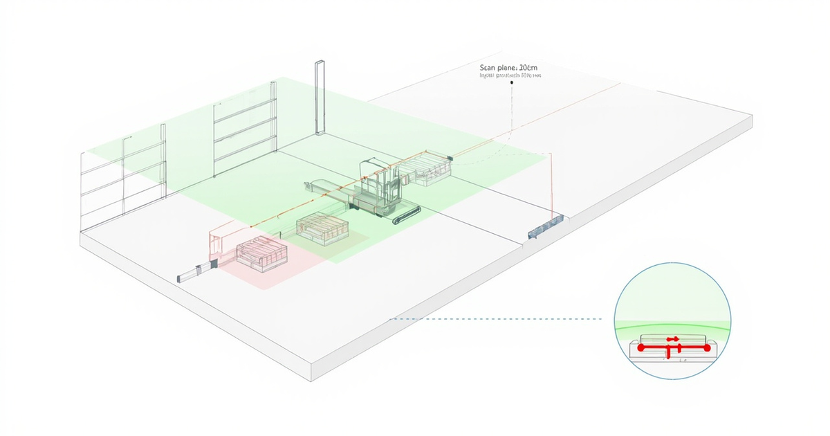
A 2D LiDAR mounted at 30cm height scans a horizontal ring at 30cm. Everything above and below that ring is invisible to the sensor. This means:
- Below the scan plane: Pallet feet (3–8cm). Cables on the floor. Dropped tools, shrink wrap scraps, forklift tines reaching into the aisle.
- Above the scan plane: Shelf overhangs. Hanging signs, low pipes, forklift masts tilted forward.
- At different heights simultaneously: A human standing next to a low cart — the 2D scanner sees one or the other depending on mount height, not both.
You can partially address this by adding more 2D scanners at different heights. Two scanners at 15cm and 80cm give you two slices instead of one. Three give you three. The problem: each additional scanner adds $150–500 in hardware, wiring complexity, and processing overhead. And you still get discrete slices, not continuous volumetric coverage.
A 3D LiDAR with 70° vertical FOV at $500–2,000 generates 100,000–300,000 pts/s with continuous vertical coverage. That's 3–7x the point density with simpler mechanical integration.
2. The Invisible Failures of 2D Perception
The hardest problems with 2D LiDAR are the ones you don't see coming, literally. We call these "invisible failures," and they fall into three categories.
2.1 The Below-Plane Blind Spot
This is the most common and most expensive failure mode. In warehouse environments, the ground between shelves is littered with small obstacles that exist entirely below a typical 2D scan plane (20–40cm height):
- Pallet feet protruding into aisles
- Shrink wrap and banding material torn from pallets
- Cables, hoses, and cleaning equipment left on the floor
- Dropped inventory items (small boxes, loose parts)
A 2D LiDAR at 25cm height will drive right over a 5cm pallet foot. The robot doesn't slow down, doesn't stop, doesn't even know the obstacle exists. If the foot catches the undercarriage, the result is a damaged pallet, a derailed robot, or both.
In our experience, ground-level obstacles account for roughly 60–70% of all AGV collision incidents in warehouse deployments. This isn't a marginal issue. It's the dominant failure mode.
2.2 The Height Mismatch Problem
2D LiDAR height is a fixed parameter. Whatever height you choose at installation determines your obstacle detection profile for the life of that deployment. Here's the problem:
Mount low (15–20cm) - You detect pallet feet and ground obstacles but miss forklift masts, shelf overhangs, and human torsos.
Mount high (80–100cm) - You detect shelves, vehicles, and humans but miss everything on the ground below your scan plane.
Mount in the middle (40–50cm) - You compromise on both ends. You see some ground obstacles and some overhead obstacles, but miss the extremes in both directions.
There is no optimal height for a single 2D scanner. Every mounting decision is a compromise. Multi-sensor setups (2–3 scanners at different heights) reduce but don't eliminate this limitation, and they introduce calibration and synchronization challenges.
2.3 The Featureless Corridor Problem
2D SLAM works by matching environmental features: corners, walls, pillars, equipment. In featureless environments (long corridors, open warehouse bays, blank hallway walls), 2D SLAM degrades rapidly. The robot's position estimate drifts, paths become unreliable, and docking accuracy suffers.
3D LiDAR addresses this by adding ceiling features into the SLAM map. Even if the floor-level scan plane is featureless, ceiling contours, light fixtures, and overhead beams provide rich localization anchors. This is particularly valuable for narrow-aisle warehouse navigation, where ceiling contour matching can be the difference between 5cm and 30cm docking accuracy.
We once deployed a 2D-LiDAR AGV in a 200m-long corridor with smooth walls. SLAM worked fine in the first 50m (lots of doors and intersections). In the remaining 150m, position drift exceeded 40cm — unacceptable for the 80cm aisle width. Adding a single 3D LiDAR that could see the ceiling fixtures brought drift back under 5cm for the entire corridor.
3. What 3D LiDAR Changes on Your Robot
Upgrading from 2D to 3D LiDAR is not just "adding a dimension." It fundamentally changes what your robot can perceive and how your navigation stack operates.
3.1 Full-Height Obstacle Detection
A 3D LiDAR with a 70° vertical FOV mounted at 1.2m height covers from approximately 26cm in front (ground level, accounting for the scan angle) to 2.6m upward. This single sensor replaces multiple 2D scanners and provides continuous coverage between those extremes — no gaps.
The result: your robot detects pallet feet, shelf overhangs, humans, and forklift masts from one sensor. No compromise on mount height. No blind zones between scan planes.
3.2 Volumetric SLAM Maps
2D SLAM generates a 2D occupancy grid, a top-down map showing where obstacles exist on a flat plane. 3D SLAM generates a 3D point cloud map that captures the full geometry of the environment: wall heights, shelf profiles, ceiling contours, and equipment shapes.
This richer map enables:
- Multi-floor operations: The same map can support navigation at different heights (e.g., loading dock level vs warehouse floor level)
- Obstacle classification: "That's a human standing next to a pallet" vs "that's a single object at sensor height"
- Map reuse across robot types: A 3D map works for a low-profile AMR and a tall forklift AGV without remapping
3.3 Near-Field Ground Detection
A 3D LiDAR with a 5cm blind zone catches ground obstacles that a 2D scanner at any height simply cannot see. The difference is not incremental. It's categorical.
Before upgrade (2D at 30cm): The robot drives over pallet feet, cables, and debris without detection.
After upgrade (3D, 5cm blind zone): The robot detects these obstacles, slows down, and navigates around them.
3.4 Ceiling-Based Localization
In environments where floor-level features are sparse (long corridors, open bays, featureless walls), ceiling features — light fixtures, HVAC ducts, beam patterns — provide a reliable localization source. Only possible with 3D LiDAR that can see upward.
The practical impact: in feature-sparse environments, 3D SLAM positional accuracy is typically 5–10x better than 2D SLAM alone. That directly translates into more reliable path following, more precise docking, and fewer "lost robot" incidents.
4. Five Scenarios Where Upgrading to 3D Pays Off
Not every project needs 3D. But these five scenarios consistently justify the upgrade.
4.1 Narrow-Aisle & Shelf Navigation
Warehouse aisles are getting narrower as facilities maximize storage density. Aisles of 1.2–1.5m are now common, with AGVs navigating through with 10–30cm of clearance on each side.
In these conditions, ground-level obstacles (pallet feet, debris) that go undetected become collision risks. Overhead shelf edges can clip sensors or cargo. And ceiling-based localization is often the only reliable position fix in long, uniform aisles.
Fewer wall contacts. More reliable docking. The ability to navigate narrower aisles with confidence.
4.2 Dynamic Human-Robot Coexistence
Modern factories increasingly position AMRs and human workers in the same space. When a human bends down to pick up a tool or crouches behind a workstation, their body profile shifts dramatically — from ~1.7m tall to ~0.5m tall.
A 2D scanner mounted at 80cm might see the human standing but miss them crouching. A 2D scanner at 20cm would see the crouching human but miss them standing. A 3D LiDAR sees both — and everything in between.
You get ISO 3691-4 compliance (human-robot coexistence safety standards), fewer safety incidents, and faster path replanning around human workers.
4.3 Multi-Environment Operations
Robots that transition between environments — warehouse to loading dock, indoor to outdoor, ground floor to mezzanine — face dramatically different obstacle profiles in each zone. A single 2D scan plane cannot adapt.
3D LiDAR's volumetric perception handles all of these transitions without reconfiguration. The robot sees ground-level curbs at the loading dock, vehicle-height obstacles on the warehouse floor, and ceiling fixtures overhead, all with one sensor.
Multi-zone operation without sensor reconfiguration or multi-sensor setups.
4.4 Outdoor and Semi-Outdoor Deployment
Outdoor environments introduce obstacles that exist entirely outside a typical 2D scan plane: low bushes, curbs, potholes, debris piles, and uneven terrain. Outdoor conditions make things harder too — rain, dust, direct sunlight reflections all degrade 2D sensor performance.
3D LiDARs with IP67 protection, dual-echo capability, and wide temperature ranges handle these conditions better. The volumetric point cloud captures terrain irregularities that a single 2D slice simply cannot represent.
Reliable outdoor operation in conditions where 2D LiDAR alone is insufficient.
4.5 Precision Docking & Manipulation
Applications that require precise positioning — automated forklifts picking pallets at specific rack positions, assembly robots aligning with workstations, charging stations with tight electrical connectors — benefit enormously from 3D perception.
3D point clouds enable sub-centimeter alignment by providing depth information at multiple points simultaneously. A 2D scanner can align the robot in two dimensions (x, y), but 3D adds the vertical dimension (z) and pitch/roll estimation for uneven surfaces.
More reliable docking (retry rates drop), faster cycle times, and the ability to handle uneven surfaces during alignment.
5. Four Scenarios Where 2D Is Still Enough
Upgrading isn't always the right move. Here are four scenarios where 2D LiDAR remains a perfectly valid choice.
5.1 Open, Flat, Controlled Environments
If your robot operates in a clean, flat environment with predictable obstacles at known heights — think hospital corridors, clean-room logistics, or open warehouse bays with wide aisles — a well-positioned 2D LiDAR at the right height captures everything relevant.
Adding 3D perception in these environments adds cost and complexity without proportional benefit. The obstacles are visible, the surfaces are flat, and the features are sufficient for 2D SLAM.
5.2 Cost-Sensitive Projects Under $200
Not every project has the budget for 3D. Educational robots, hobbyist platforms, proof-of-concept prototypes, and some entry-level commercial products genuinely cannot justify $500–2,000 for a 3D sensor.
In these cases, a $200 2D scanner with supplementary ultrasonic sensors for close-range detection provides a functional perception system at a fraction of the cost. It's not ideal, but it's honest engineering within constraints.
5.3 Fixed-Path, Low-Speed Applications
Some AGVs follow well-defined, low-speed routes where the environment changes rarely. Magnetic-tape-guided AGVs with 2D safety scanners, simple line-following robots, and low-speed cleaning robots in controlled areas can operate effectively with 2D perception.
At 0.3–0.5 m/s, the robot has more time to react, and missed obstacles hurt less.
5.4 Supplementary Safety Scanning
Some systems use a 3D LiDAR for primary navigation and add 2D scanners as dedicated safety zone monitors. In this configuration, the 2D scanner isn't doing navigation — it's providing a simple, reliable, fast-updating safety curtain at a specific height (e.g., knee-level pedestrian detection).
For this use case, 2D LiDAR's fast scan rate (25–40 Hz) and simplicity are genuine advantages. You don't need 3D perception for a single-height safety zone — you need speed and reliability.
Don't confuse "2D is enough" with "2D is optimal." There's a difference between a project where 2D meets minimum requirements and a project where 2D is genuinely the best tool. In 2026, the gap between these two categories is narrowing fast.
6. Upgrade Cost vs. Benefit: An Honest Analysis
Here's the full cost picture, including the hidden costs that catch teams off guard.
Hardware Cost Comparison
| Component | 2D LiDAR Setup | 3D LiDAR Setup |
|---|---|---|
| Primary sensor | $150–500 (single 2D unit) | $500–2,000 (single 3D unit) |
| Additional sensors for coverage | $300–1,000 (2–3 extra 2D units for multi-height) | $0 (single unit provides full coverage) |
| Ultrasonic supplementary | $50–150 (4–8 units for blind zone fill) | $50–100 (optional, fewer units needed) |
| Mounting hardware | $50–200 (multi-bracket system) | $20–50 (single bracket) |
| Total sensor hardware | $550–1,850 | $570–2,150 |
The hardware gap is smaller than most people expect. A multi-sensor 2D setup (the realistic configuration for adequate coverage) costs nearly as much as a single 3D unit.
Development & Integration Costs
| Factor | 2D Stack | 3D Stack |
|---|---|---|
| SLAM algorithm development | 1–2 weeks (well-documented, mature) | 2–4 weeks (more parameters, more tuning) |
| Obstacle avoidance adaptation | 1 week (planar costmap) | 2–3 weeks (3D costmap, voxel filtering) |
| Compute platform requirements | Low (Raspberry Pi 4 can run 2D SLAM) | Medium (Jetson Orin Nano or equivalent recommended) |
| Calibration complexity | Low (single sensor or simple multi-sensor) | Medium (extrinsic calibration, coordinate transforms) |
| Testing & validation | 1–2 weeks | 2–3 weeks |
The real cost difference isn't in hardware — it's in development time and compute requirements. Expect 3–6 weeks of additional engineering effort when migrating from a mature 2D stack to 3D. This is a one-time cost, but it's real.
Operational Benefits That Offset Costs
Based on our deployment data:
- Collision rate reduction: 60–80% fewer ground-level obstacle collisions after upgrading to 3D (primarily due to near-field detection capability)
- Docking reliability: Retry rates drop from 15–20% (2D) to 2–5% (3D with volumetric alignment)
- SLAM reliability: "Lost robot" incidents drop by 80–90% in feature-sparse environments
- Maintenance reduction: Fewer sensor units means fewer calibration points, fewer wiring connections, and fewer failure modes
- Environment adaptability: A single 3D unit handles environment transitions that would require sensor reconfiguration with 2D
ROI timeline: For a fleet of 10+ AGVs operating in challenging environments (narrow aisles, dynamic obstacles, multi-zone), the upgrade typically pays for itself within 6–12 months through reduced collision damage, fewer service calls, and higher operational uptime. For a detailed breakdown, see our AGV LiDAR TCO analysis (3-year model).
7. Key Specs When Choosing a 3D LiDAR
These are the parameters that actually matter for AGV/AMR applications — and the pitfalls to avoid.
Blind Zone (Most Important)
The near-field blind zone determines what your robot can detect at close range. For AGVs replacing 2D scanners, the blind zone is the #1 spec to evaluate.
Target: ≤5cm for warehouse and delivery applications. A 10cm blind zone is the absolute maximum — anything larger means you'll still miss small ground obstacles.
Vertical Field of View
The vertical FOV and its distribution (upward vs downward coverage) determine how much of the environment your robot can see from a single mount point.
Target: ≥59° for general AGV use. ≥70° if you need ceiling-based localization. Pay attention to the distribution — -10°/+60° is better for AGVs than -35°/+35°.
Point Rate & Frame Rate
Higher point rates provide richer environmental data for SLAM and obstacle classification. Frame rate determines how quickly your robot's perception updates.
Target: ≥100,000 pts/s for reliable 3D perception. Frame rate ≥10 Hz for dynamic environments with humans.
Power Consumption
Every watt of sensor power reduces your robot's operating time. On battery-powered platforms, this directly affects the business case.
Target: ≤5W for small/medium platforms. ≤8W acceptable for large AGVs with substantial battery packs.
IP Rating
Even "indoor" robots encounter water, dust, and condensation. The cost difference between IP54 and IP67 is minimal.
Target: IP67 for any robot that might encounter moisture, dust, or cleaning processes. Don't learn this the hard way.
Weight & Form Factor
The sensor's physical size and weight determine where it can be mounted and how it affects the robot's dynamics.
Target: ≤500g for small AMRs and delivery robots. ≤1kg acceptable for large AGVs.
Built-in IMU & Time Sync
SLAM algorithms need IMU data for motion compensation. A built-in IMU with hardware time synchronization (PTP v2) saves an external module, eliminates timestamp alignment headaches, and provides tighter sensor fusion.
Target: Built-in 6-axis IMU with PTP v2 support. This is increasingly standard on quality 3D LiDARs.
| Parameter | Budget Option | Recommended | Premium |
|---|---|---|---|
| Blind zone | ≤15cm | ≤10cm | ≤5cm |
| Vertical FOV | ≥45° | ≥59° | ≥70° |
| Point rate | ≥50k pts/s | ≥100k pts/s | ≥200k pts/s |
| IP rating | IP54 | IP65 | IP67 |
| Power | ≤8W | ≤6W | ≤5W |
| Weight | ≤1kg | ≤600g | ≤500g |
| Built-in IMU | No | Yes | Yes + PTP v2 |
| Dual echo | No | No | Yes |
8. The M360 as a 2D-to-3D Upgrade Path
Full disclosure: the M360 3D LiDAR is our product. But we designed it specifically as a 2D-to-3D upgrade option, and understanding its fit for this use case is directly relevant to the upgrade decision.
See also: M360 Parameter Comparison for detailed specs.
Why the M360 Fits as a Drop-In Upgrade
When teams upgrade from 2D to 3D, the biggest practical concerns are usually about integration: Will it fit? Will it work with my battery? Do I need a new compute platform?
The M360 was designed to minimize these friction points:
Form Factor: 408g, 78x78x81mm
At 408g, the M360 is lighter than most 2D scanner + bracket combos. The compact form factor means it can replace a 2D unit in the same mounting location without structural changes. For robots designed around a specific sensor envelope, this matters.
Power: <4.5W, 12–32V Input
Under 4.5W means the M360 draws less power than many 2D LiDARs (which typically consume 3–5W). The wide 12–32V input range covers common battery configurations: 3S (11.1V), 4S (14.8V), 6S (22.2V), and 8S (29.6V). No DC-DC converter needed for most setups.
5cm Blind Zone
This is the single biggest upgrade value for most AGV applications. The 5cm blind zone catches pallet feet, cables, and debris that a 2D scanner — at any height — simply cannot see.
70° x 360° FOV
The 70° vertical FOV (-10° to +60°) provides both ceiling and ground coverage from a single top-mount position. Ceiling-based localization and ground-level detection at the same time.
Built-in IMU + PTP v2
The 6-axis IMU with hardware-level PTP v2 time synchronization eliminates the need for an external IMU module and manual timestamp alignment. That saves $50–150 in hardware cost and 1–2 weeks of integration work.
Where the M360 Doesn't Replace 2D
Honest limitations:
- Safety-rated scanning: The M360 is designed for navigation and obstacle avoidance, not as a certified safety scanner per IEC 61496 Type 3. If your application requires certified safety scanners, you'll still need those alongside the M360.
- Ultra-low-cost builds: If your total perception budget is under $200, 2D remains the only viable option.
- Compute-constrained platforms: Processing 200,000 pts/s requires a Jetson Orin Nano or equivalent. A Raspberry Pi 4 can handle 2D SLAM but struggles with 3D point clouds at this data rate.
9. Practical Migration: From 2D Stack to 3D Stack
This plan assumes a ROS/ROS2-based navigation stack — which covers the majority of AGV/AMR platforms.
Phase 1: Evaluation (Week 1–2)
- Procure one evaluation unit of your chosen 3D LiDAR
- Mount on your existing robot alongside the current 2D sensor (parallel operation)
- Run both sensors simultaneously for 5–7 days in your actual environment
- Collect data: point cloud quality, blind zone performance, noise levels, compute load
- Compare: what does the 3D sensor see that 2D misses? What's the compute impact?
Phase 2: Software Migration (Week 3–6)
- SLAM: Switch from 2D SLAM (Cartographer/GMapping) to 3D LiDAR SLAM (FAST-LIO2, LIO-SAM, or Point-LIO). FAST-LIO2 is our recommended starting point — it's computationally efficient and well-documented.
- Costmap: Migrate from 2D costmap to 3D voxel costmap or octomap. This enables volumetric obstacle representation.
- Obstacle avoidance: Adapt DWA or TEB local planner to work with 3D point cloud input instead of 2D laser scan.
- Localization: If using AMCL, transition to 3D LiDAR-based localization or multi-modal localization (3D LiDAR + wheel odometry + IMU).
Phase 3: Validation & Deployment (Week 7–8)
- Remove the 2D sensor. Run the robot on 3D-only perception.
- Test all operational scenarios: normal navigation, docking, obstacle avoidance, multi-robot operation.
- Measure: collision rate, docking accuracy, SLAM drift, compute utilization.
- Compare against baseline 2D performance metrics.
- Document and deploy to production fleet.
Keep your 2D SLAM code as a fallback during the migration. If the 3D stack encounters issues in a specific zone, you can temporarily revert to 2D operation while debugging. This safety net significantly reduces migration risk.
10. Your Decision Framework
Answer these questions honestly:
| Question | If Yes - Consider 3D | If No - 2D May Suffice |
|---|---|---|
| Does your robot encounter obstacles below 20cm or above 150cm? | 3D addresses both | 2D at optimal height works |
| Does your robot share space with humans who move unpredictably? | 3D provides full-body detection | 2D at body height is adequate |
| Does your robot operate in narrow aisles (<1.5m)? | 3D enables ceiling localization + ground detection | 2D works if aisles are wide and clean |
| Does your robot transition between different environments? | 3D handles transitions automatically | 2D needs reconfiguration per zone |
| Has your robot had ground-level collision incidents? | 3D's near-field detection addresses root cause | 2D may work if collisions are rare |
| Is your perception budget over $500? | 3D is affordable at this level | 2D fits within tighter budgets |
| Does your compute platform support 3D point cloud processing? | 3D stack runs well on Jetson Orin+ | Stick with 2D on Pi-class hardware |
If you answered "yes" to 3 or more questions, upgrading to 3D LiDAR will likely deliver measurable operational improvements. If you answered "yes" to 5 or more, the upgrade is a clear win.
If you answered "no" to most questions — your environment is controlled, your aisles are wide, your obstacles are predictable, and your budget is tight — then 2D LiDAR is a perfectly valid engineering choice. Don't upgrade just because 3D is newer. Upgrade because it solves real problems you're experiencing.
If you haven't hit these problems yet and your environment doesn't create them, a 2D sensor that works is better than a 3D sensor that adds complexity. Don't upgrade just because you can.
See also: AGV/AMR LiDAR Selection Guide for detailed selection criteria across AGV scenarios.
We've helped dozens of teams navigate this upgrade. If you're evaluating options, we're happy to share benchmark data or arrange evaluation units. Contact SmartBotParts.
📖 Related Reading
-
AGV/AMR LiDAR Selection Guide (2026)
Comprehensive guide: specs, scenarios, and decision checklist.
-
Smart Forklift Precision Handling: M360 LiDAR Case Study
Real-world 3D LiDAR upgrade results in industrial logistics.
-
Substation Inspection: How M360 Solves 40° Staircase Navigation
3D LiDAR performance in extreme industrial environments.
-
High-Precision Industrial Scanning: M360 LiDAR in Factory Applications
3D scanning for factory renovation, warehouse modeling, and maintenance.
-
Complete AMR Fleet Migration Guide: 2D to 3D LiDAR in 2026
Step-by-step migration framework covering sensor selection, SLAM migration, and safety compliance.
Considering an Upgrade from 2D to 3D LiDAR?
M360 delivers 5cm near-blind zone, 70° vertical FOV, and <4.5W low power — the ideal upgrade path.
View M360 Specs → Get Upgrade Plan →🛒 M360 3D LiDAR:5cm blind zone | 70°×360° FOV | IP67 | <4.5W | Dual echo optional
View full parameter comparison →
Frequently Asked Questions
Is upgrading from 2D to 3D LiDAR worth it for warehouse AGVs?
In most warehouse deployments — especially those with narrow aisles (under 1.5m), mixed obstacle heights, and dynamic human-robot environments — 3D LiDAR pays for itself within 6–12 months. The primary ROI driver is collision reduction: ground-level obstacle collisions typically drop 60–80% because 3D coverage eliminates the below-plane blind spot that 2D scanners inherently have. If your aisles are wide, obstacles are predictable, and you rarely hit pallet feet or floor debris, 2D remains viable.
Can I use multiple 2D LiDARs instead of upgrading to 3D?
You can, and some teams do — mounting two or three 2D scanners at different heights (e.g., 15cm and 80cm) gives you additional scan slices. But the total hardware cost for a multi-2D setup ($550–1,850 depending on configuration) often approaches a single 3D unit ($500–2,000). The tradeoff: you still get discrete slices with gaps between them, not continuous volumetric coverage. Multi-2D also adds calibration complexity and more wiring to maintain.
Does 3D LiDAR require more compute power than 2D?
Yes. Processing 100,000–300,000 points per second for 3D SLAM (FAST-LIO2, LIO-SAM) needs something like an NVIDIA Jetson Orin Nano. A Raspberry Pi 4 that handles 2D SLAM comfortably will struggle with 3D point cloud processing at full rate. Expect your compute budget to increase by $100–300 per robot for the processing upgrade.
What is LiDAR blind zone and why does 5cm vs 10cm matter?
The blind zone is the minimum distance at which the LiDAR can detect an object. For indoor AGVs, the most common collision-causing obstacles — pallet feet (3–8cm), shrink wrap scraps (2–5cm), cables — sit within this range. A 5cm blind zone catches these. A 10cm blind zone misses a 5cm pallet foot entirely. In practice, that difference shows up as 60–70% of AGV collisions in warehouse environments being ground-level incidents that a smaller blind zone would prevent.
Can I run 2D and 3D LiDAR simultaneously during migration?
Yes, and that's the recommended approach. Run both sensors in parallel on one robot for 5–7 days in your actual environment. Compare what the 3D sensor detects that 2D misses, measure the compute impact, and validate SLAM performance. Keep the 2D stack as a fallback during the transition. This parallel-testing phase typically adds 1–2 weeks but significantly reduces migration risk.
Does 3D LiDAR work with ROS and ROS2?
Yes. The main shift is in the SLAM algorithm — instead of 2D SLAM packages like Cartographer or GMapping, you'd use 3D LiDAR SLAM like FAST-LIO2, LIO-SAM, or Point-LIO. All three have mature ROS/ROS2 support. The costmap and obstacle avoidance layers also need updating from 2D planar costmaps to 3D voxel-based representations (octomap or voxel layer).
How much does a 3D LiDAR cost compared to 2D?
A quality 2D scanner runs $150–500. A 3D LiDAR suitable for AGV navigation runs $500–2,000 in 2026 — roughly 3–5x more. But the effective gap narrows when you factor in multi-sensor 2D setups: adding two or three 2D units for adequate multi-height coverage brings the total 2D hardware cost to $550–1,850, which is comparable to a single 3D unit that provides better coverage.
What FOV do I need for ceiling-based localization?
For ceiling contour matching to augment SLAM in feature-poor environments (long corridors, uniform aisles), you want at least 70° vertical FOV with upward-biased distribution — ideally -10° to +60°. This lets a top-mounted sensor see both ground-level obstacles and ceiling fixtures (lights, HVAC ducts, beam patterns) from a single position. A narrower FOV or symmetric distribution limits the ceiling coverage available for localization.
© 2026 SmartBotParts. All rights reserved.
The parameters, cost estimates, and performance data referenced in this article are based on manufacturer specifications and real-world deployment testing. Actual performance may vary depending on environmental conditions, installation, and configuration. Always verify specifications with the latest official product documentation.