
RoboSense shipped 185,500 LiDAR units to robotics customers in Q1 2026 alone — a 1,458.8% year-over-year jump. The message is hard to ignore: 3D LiDAR for mobile robots has crossed from early-adopter territory into mainstream production. For AMR teams still running fleets on 2D LiDAR arrays, the upgrade question isn't "if" anymore. It's "how."
This guide walks through the entire migration — from auditing your current setup to selecting the right 3D sensor and scaling across your fleet.
Why Upgrade from 2D LiDAR to 3D LiDAR?
The Limitations of 2D LiDAR in Real-World AMR Operations
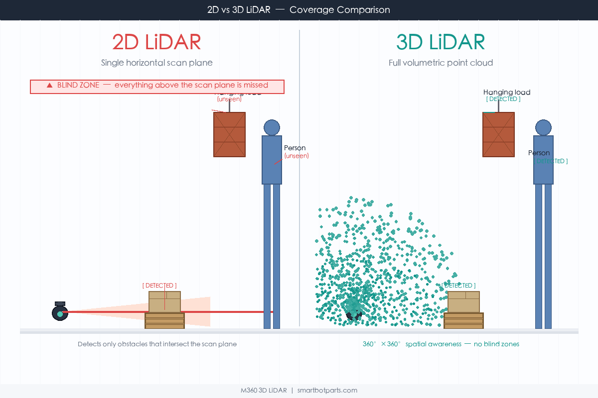
A single 2D LiDAR scans one horizontal plane. In a controlled lab, that's fine. On a warehouse floor at 2 AM, things get messy.
Low-hanging forklift tines don't register. Pallet overhangs extending below the scan line go unnoticed. Floor depressions, dropped shrink wrap, and cables — all invisible to a sensor that only sees a thin ring at one height. Teams compensate by stacking sensors: two or three 2D LiDAR units at different angles, a 3D camera for overhead clearance, ultrasonic sensors for close-range backup. The sensor count climbs fast, and so does the BOM cost, wiring complexity, and calibration overhead.
Then there's the maintenance. Each sensor introduces a potential failure point. Calibrating four or five sensors into a coherent data pipeline takes engineering hours. When one unit drifts — and they do — your AMR's navigation quality degrades in ways that are hard to diagnose.
What 3D LiDAR Changes
A single 3D LiDAR captures the environment in three dimensions. Instead of a single ring, you get a volumetric point cloud covering 360° horizontally and typically 59° to 70° vertically. For a deeper look at the differences, see our detailed 2D vs 3D LiDAR comparison.
That means overhead obstacles, floor-level debris, and everything in between gets detected by one sensor. No multi-sensor arrays to fuse, no blind zones between scan planes. The point cloud itself carries richer information — height, shape, and reflectivity — which makes obstacle classification more reliable. Your AMR can distinguish between a person and a pallet from the sensor data alone, without relying on a secondary camera.
The sensor architecture simplifies dramatically. Fewer hardware units, fewer data interfaces, fewer points of calibration failure.
The ROI Equation: When 3D LiDAR Actually Costs Less
The price argument against 3D LiDAR used to hold weight. In 2023, a single 3D unit cost three to five times what a 2D LiDAR did. That gap has compressed considerably. Meanwhile, the hidden costs of running multi-2D setups — integration labor, ongoing calibration, per-sensor maintenance contracts, chassis space occupied by multiple mounting brackets — never show up on a simple sensor price comparison.
Here's the math that more teams are running:
- Sensor consolidation: one 3D LiDAR replaces 3–5 individual sensor units
- Wiring and connectors: fewer power lines, fewer data interfaces, simpler harness routing
- Calibration: a single sensor to tune instead of a multi-sensor transform chain
- Software complexity: point cloud processing from one source, not sensor fusion from four
On top of that, better obstacle detection means AMRs can move faster with confidence. An AMR that safely averages 1.8 m/s instead of 1.2 m/s because it sees obstacles 40% sooner delivers 50% more throughput per unit. At fleet scale, that's the difference between ordering 20 robots and ordering 12.
The mobile robotics LiDAR market — valued at $1.12 billion in 2025 — is projected to hit $7.15 billion by 2034. The industry is already there.
Key 3D LiDAR Specs to Evaluate for AMR Migration
Not all 3D LiDAR sensors are built the same way, and the wrong choice can make your migration more painful than staying with 2D. These are the parameters that matter most for AMR applications.
Field of View (FoV) Requirements
Horizontal coverage needs to be 360°. No exceptions for omnidirectional AMRs. If you're running a line-following AGV on fixed paths, you might get away with a forward-facing unit, but that's not the upgrade scenario this guide addresses.
Vertical FoV is where the real differentiation happens. A 70° vertical spread (e.g., -10° to +60°) catches overhead obstructions at +60° while still seeing the floor at -10°. Sensors with tighter vertical angles — say 30° — will miss either ceiling-level obstacles or floor clutter, depending on how they're mounted. For warehouse AMRs navigating under shelf racks, the low-angle coverage matters a lot. See our near-blind zone comparison of 6 LiDAR sensors for detailed measurements.
Detection Range vs. Facility Layout
Most indoor AMR applications don't need 200-meter range. A warehouse aisle is typically 3–5 meters wide, and the furthest obstacle you need to detect for braking is around 20–40 meters ahead — depending on your AMR's max speed and payload weight.
What does matter is close-range performance. A sensor with a 0.05 m (5 cm) blind zone can detect objects right next to the robot chassis. Sensors with 0.5 m or larger blind zones create a dangerous dead zone immediately around the vehicle — exactly where dropped items, ankles, and forklift tines tend to appear.
Point Cloud Resolution & Frame Rate
For real-time obstacle avoidance, you need point cloud updates at 20 Hz or higher. Faster is better — 30–40 Hz gives your motion planning stack more current data to work with, especially at speeds above 1.5 m/s.
Resolution matters for object classification. Denser point clouds let your software distinguish between a flat wall and a person standing against it. Sparse data forces conservative behavior: if your AMR can't tell whether something is a box or a person, it has to stop, and stopping means slower throughput.
Size, Weight & Power Consumption
This gets overlooked until your mechanical engineer starts cursing. A sensor that weighs 1.2 kg and draws 15 W might work fine on a 500 kg forklift AGV. On a 30 kg picking AMR with a 300 Wh battery, every gram and every watt counts.
Compact sensors in the 400–500 g range that draw under 5 W are ideal for small and medium AMRs. They mount on top of the chassis without requiring structural reinforcement, and they don't drain your battery budget.
Integration & Ecosystem
ROS/ROS2 driver availability is table stakes at this point. Beyond that, check for: SDK documentation quality, point cloud output formats (standard PCD/ROS PointCloud2), time synchronization support (PTP/IEEE 1588 for multi-sensor setups), and whether there's an active user community posting issues and solutions. A sensor with no ROS driver or a half-maintained GitHub repo will cost you weeks of integration work.
Step-by-Step Migration Framework
Step 1: Audit Your Current 2D LiDAR Setup
Before buying anything, document what you have. How many 2D LiDAR units per robot? Where are they mounted and at what angles? What data interfaces are they connected through (Ethernet, CAN, UART)? What SLAM algorithm are you running, and what sensor inputs does it expect? If you're still in the evaluation phase, our AGV/AMR LiDAR Selection Guide covers sensor criteria in depth.
Also document your pain points — not in general terms, but specifically. "Missed a pallet overhang at 22:14 on June 3rd" is actionable. "Sometimes misses things" isn't.
Step 2: Map 3D LiDAR to Your Use Cases
Not every AMR application benefits equally from 3D LiDAR. Warehouse navigation with frequent human interaction and variable obstacles? High benefit. Fixed-path line following between two stations? The ROI case is weaker — though not nonexistent if floor debris is a recurring issue.
Consider your specific scenarios: narrow aisle navigation, docking precision at charging stations, mixed indoor/outdoor transitions, and SKU handling that requires close-range detection. Rank these by how much 3D perception would improve performance versus your current setup.
Step 3: Prototype & Benchmark
Don't roll out to the fleet. Start with one or two units on your most demanding use case. Measure detection rate (did it catch obstacles the 2D setup missed?), navigation accuracy (path deviation under load), and cycle time (faster completion means better throughput).
Set a two-week benchmark window. One week isn't enough to surface edge cases; one month is too long if the results are clearly positive and you're burning daylight on the migration. For reference, check out our 6-month autonomous forklift comparison test for a real-world benchmark methodology.
Step 4: Validate Safety Compliance
ANSI/RIA R15.08 defines safety requirements for industrial mobile robots, and any sensor change that affects the protective field (the zone around the robot where obstacles trigger a safety stop) needs re-validation. This isn't optional — it's a regulatory and liability requirement.
Document your testing methodology, keep logs of obstacle detection performance at various speeds and under various lighting conditions, and verify that your safety-rated protective fields maintain coverage with the new sensor. If you're selling AMRs to end customers, this step matters even more.
Step 5: Scale & Monitor
Deploy in phases — not because 3D LiDAR is risky, but because phased rollout lets you catch integration issues that only appear under real fleet conditions. Start with 10–20% of the fleet, monitor for a month, then expand.
Track the same metrics from your prototype phase at fleet scale: detection incidents, navigation accuracy, cycle time, and any increase in false positives (the robot stopping for nothing, which hurts throughput).
Top 3D LiDAR Sensors for AMR Upgrades in 2026
M360 — Compact 3D LiDAR for Small-to-Medium AMRs
The M360 is a compact 3D LiDAR designed for low-speed robotics and AMR applications. It offers 360° horizontal coverage with a 70° vertical FoV (-10° to +60°), which provides solid overhead and floor-level detection from a single mounting position. Detection range spans 0.05 m to 50 m at 90% reflectivity, with a tight 5 cm blind zone.
At 408 g and under 4.5 W power draw, the M360 is sized for the small and medium AMR segment where weight and power budget are real constraints. It runs on 12–32 V DC, which covers the range of most AMR battery systems without needing a separate voltage converter. Range accuracy holds within 2 cm at 10 m, and the built-in 6-axis IMU supports motion compensation for SLAM.
The IP67 housing handles dust and water exposure in warehouse environments. Non-repetitive scanning patterns fill the vertical FoV over time, building denser point clouds without needing more channels. ROS/ROS2 drivers are available, and the sensor outputs standard point cloud data over 100BASE-TX Ethernet with PTP time synchronization.
Best fit: Small-to-medium AMRs where sensor consolidation, low power, and compact size are priorities. Especially suitable for warehouse picking robots, delivery AMRs, and cleaning robots operating indoors.
RoboSense Airy — Ultra-Thin Sensor for Tight Clearances
RoboSense's Helios platform — particularly the Airy variants — targets the robotics market. The Helios 16 offers 150 m range with a 30° vertical FoV and 16 channels, while newer Airy models push vertical coverage to 70° with a slimmer profile. The Airy is thin (around 7 mm exposed window height on some variants), which appeals to designs with tight vertical clearance.
Beyond the Airy, teams also considering alternatives to the Livox Mid-360 should check out 7 alternatives to the Livox Mid-360 for more options. RoboSense's own shipment data — 185,500 robotics LiDAR units in Q1 2026 — suggests mature production volume and stable supply chains.
Best fit: Teams already using RoboSense sensors, or AMRs that need ultra-thin sensor profiles to fit under low-clearance structures.
Hesai JT128 — Hyper-Hemispheric 128-Channel Sensor
The Hesai JT128 is a 128-channel sensor with an unusually wide 360° × 187° hyper-hemispherical FoV. Detection range reaches 60 m, and the 128 vertical channels deliver dense point clouds with good object classification capability. At roughly 900 g, it's heavier than the M360 but still manageable for medium AMRs.
The hyper-hemispherical design means you can detect obstacles above and below the robot without tilting or adding a second sensor. This makes the JT128 particularly attractive for applications involving ramps, loading docks, or multi-level environments.
Best fit: AMRs operating in complex vertical environments — loading docks, multi-level facilities, or applications that need exceptional point cloud density for classification tasks.
Quick Comparison
| Sensor | Horiz. FoV | Vert. FoV | Range | Blind Zone | Weight | Power | ROS Support |
|---|---|---|---|---|---|---|---|
| M360 | 360° | 70° (-10°~+60°) | 0.05–50m | 5 cm | 408 g | <4.5 W | ROS/ROS2 |
| RoboSense Airy | 360° | 70° (varies by model) | Up to 40m (varies) | 10–20 cm | ~300 g | ~5 W | ROS/ROS2 |
| Hesai JT128 | 360° | 187° (hyper-hemispheric) | 0–60m | ~20 cm | ~900 g | ~12 W | ROS/ROS2 |
For a detailed spec-for-spec comparison, check out the M360 vs MID-360 breakdown on our site.
Common Mistakes to Avoid During Migration
Underestimating compute requirements. Processing a 3D point cloud is heavier than processing a 2D scan line. If your AMR runs on a Raspberry Pi 4, you may need to upgrade the compute platform alongside the sensor. Plan for this upfront — it's often the line item people forget until the prototype stutters at 8 Hz.
Skipping the prototype phase. Teams that buy fleet quantities upfront and skip benchmarking tend to discover integration issues in production, which are more expensive to fix. Always prototype first.
Mounting position matters more than you think. A 3D LiDAR mounted too low will miss overhead obstacles. Mounted too high, the floor-level detection degrades. The M360's -10° to +60° vertical FoV gives you a good starting range, but fine-tuning the mounting angle and height for your specific chassis and application is worth the afternoon it takes.
Not updating your SLAM algorithm. If you're running a 2D SLAM stack (Gmapping, Cartographer in 2D mode, etc.), switching to 3D LiDAR means switching to a 3D SLAM algorithm (RTAB-Map, LIO-SAM, or FAST-LIO). The migration isn't just hardware — your software pipeline needs the same attention.
Ignoring time synchronization. When you move from multiple 2D sensors (each with its own timing) to a single 3D LiDAR, PTP synchronization becomes important if you're combining the LiDAR with cameras or IMU data. The M360 supports IEEE 1588-2008 (PTP v2) out of the box, which simplifies this for multi-sensor setups. For teams running multiple LiDAR units on one robot, see our guide to multi-device anti-interference solutions.
Frequently Asked Questions
Can I mix 2D and 3D LiDAR during migration?
Yes. A hybrid approach works well for phased rollouts. You can run the 3D LiDAR as the primary navigation sensor while keeping one 2D unit as a safety cross-check during the transition period. Most SLAM frameworks can ingest both data sources simultaneously.
How long does a typical fleet migration take?
For a fleet of 20–50 AMRs, expect 3–6 months from prototype sign-off to full deployment. The bottleneck is usually software integration and safety validation, not hardware installation. Plan for two weeks per phase: prototype benchmark, safety testing, and fleet rollout.
What's the realistic ROI timeline?
Most teams report measurable improvement in obstacle detection and cycle time within the first month of 3D operation. The full ROI — accounting for sensor cost, integration labor, and throughput gains — typically lands between 12 and 24 months for medium-sized fleets. Larger fleets see faster payback due to volume pricing and higher cumulative throughput gains.
Do I need to change my SLAM software?
Almost certainly. 2D SLAM algorithms process planar scan data and don't natively handle 3D point clouds. Mature 3D SLAM options — FAST-LIO, LIO-SAM, and RTAB-Map among them — have active communities and solid ROS/ROS2 integration. The migration effort is real but well-documented. See our M360 SLAM algorithm comparison for a head-to-head benchmark.
The Bottom Line
The shift from 2D to 3D LiDAR in AMR fleets is no longer a forward-looking bet. It's happening now, driven by falling sensor prices, maturing software stacks, and the practical advantages of consolidating multiple sensors into one. The teams that migrated in 2025 are already seeing the benefits in throughput and maintenance reduction. If your fleet is still running on 2D arrays, 2026 is the year to make the move.
Start with a prototype. Benchmark against your current setup. Validate safety compliance. Then scale.
For teams evaluating 3D LiDAR options, the M360 3D LiDAR is worth a close look — compact, low-power, with the specs that matter most for AMR navigation. Or contact us to discuss your specific migration requirements.
© 2026 SmartBotParts. All rights reserved.
Product specifications in this article are sourced from publicly available manufacturer documentation as of June 2026. Always verify with the latest datasheets before deployment. All product names are trademarks of their respective manufacturers.