A renovation team arrives at a 1960s office building. No original drawings exist. The MEP systems have been patched together over six decades by contractors who never documented their work. The structural engineer needs accurate as-built data to sign off on the seismic retrofit.
Twenty years ago, this meant tape measures, grid paper, and weeks on site. Today, a surveyor walks through the building with a handheld LiDAR scanner. In 90 minutes, the entire floor is captured as a dense 3D point cloud. Two weeks later, the engineer has a Revit model where every beam, duct, and pipe matches reality within ±15mm.
This is scan-to-BIM — and for teams considering upgrading from 2D to 3D LiDAR, handheld systems are making it faster, cheaper, and more accessible than ever.
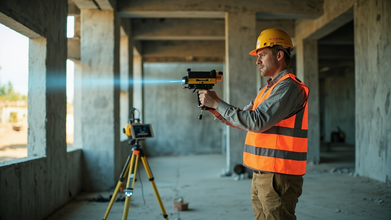
What Is Scan-to-BIM and Why Handheld LiDAR?
Scan-to-BIM means converting real-world spatial data captured by laser scanning into a Building Information Model. The result isn't just a 3D picture — it's an intelligent model where each element (walls, pipes, beams) carries metadata: material type, dimensions, system classification. That's what makes it a BIM, not a mesh.
The pipeline is straightforward: capture point cloud data in the field → register and clean the data → import into BIM software → model building elements against the point cloud → validate accuracy.
Why handheld over tripod-mounted scanners
Tripod-based terrestrial laser scanners (Leica RTC360, FARO Focus) have been the industry standard for years, and for good reason — sub-millimeter accuracy and long range. But they come with tradeoffs:
- Setup time: Each scan position takes 3–8 minutes for setup, capture, and repositioning. A typical building requires 50–200 individual scan positions.
- Labor: Two-person crew minimum. One operates the scanner, the other places targets.
- Speed: A 50,000 sq ft commercial building typically takes 1–2 days of scanning with a terrestrial system.
- Cost: Survey-grade terrestrial scanners run $30,000–$80,000.
Handheld SLAM-based LiDAR scanners change this equation. The operator walks through the space continuously while the sensor builds a point cloud in real time using SLAM (Simultaneous Localization and Mapping). No targets. No setup between positions. One person.
- Capture speed: 5–10x faster than tripod-based scanning for interior spaces. That same 50,000 sq ft building? 2–4 hours with a handheld unit.
- Labor: Single operator. Walk in, walk out.
- Access: Handheld units fit into tight spaces — mechanical rooms, crawl spaces, narrow corridors — where tripod scanners can't physically go.
- Cost: $4,000–$15,000 for a complete handheld scanning system vs $30,000–$80,000 for terrestrial.
The tradeoff is accuracy. Handheld SLAM systems deliver centimeter-level accuracy (typically ±10–20mm globally, ±5–10mm locally), which is sufficient for most renovation, facility management, and construction documentation applications. Sub-millimeter accuracy requirements (heritage conservation, structural analysis, precision fabrication) still call for terrestrial or hybrid approaches.
Where handheld LiDAR fits in scan-to-BIM
| Application | Handheld LiDAR | Terrestrial LiDAR | Hybrid |
|---|---|---|---|
| Facility management documentation | Primary | Overkill | — |
| Renovation / tenant improvement | Primary | High-detail areas | Detail zones |
| MEP as-built survey | Primary (speed) | Confirmation | Mechanical rooms |
| Heritage conservation | Supplemental | Primary | Interior + exterior |
| Construction progress monitoring | Primary | QA checkpoints | — |
| Structural analysis | Not recommended | Primary | — |
For the majority of commercial scan-to-BIM work — documenting existing conditions for renovation, facility management, or construction coordination — handheld LiDAR is now the starting point. Terrestrial scanners come in for detail zones, and the two datasets merge in post-processing.
How Handheld LiDAR Works for Scan-to-BIM
Core Technology Stack
A handheld SLAM scanner isn't just a LiDAR sensor on a stick. It's a sensor fusion system combining three components:
3D LiDAR sensor — emits laser pulses and measures return times to build distance data. Handheld units typically use solid-state or semi-solid designs with non-repetitive scanning patterns that build dense point coverage over time. Key specs include point rate (100,000–300,000 pts/s), detection range (0.05–50m for indoor units), and field of view.
IMU (Inertial Measurement Unit) — 6-axis (3-axis accelerometer + 3-axis gyroscope) provides high-frequency motion data. The SLAM algorithm fuses this with LiDAR data to estimate the scanner's trajectory through space in real time. The quality of the IMU and its time synchronization with the LiDAR directly affects SLAM drift — the accumulation of positional error over long scans. Hardware-level PTP (Precision Time Protocol) synchronization between IMU and LiDAR reduces timestamp misalignment from milliseconds to nanoseconds.
SLAM algorithm — Simultaneous Localization and Mapping estimates the scanner's position while building the map. Popular algorithms for handheld scanning include FAST-LIO2 (computationally efficient, good for resource-constrained platforms), LIO-SAM (factor-graph approach, accurate with loop closures), and Point-LIO (point-level, handles fast motion well). SLAM quality depends on environmental features: corridors with distinct geometry (doors, corners, columns) produce tight localization, while long featureless hallways cause drift.
Some handheld scanners also include a camera for colorized point clouds, which helps with element identification during BIM modeling — you can see the texture of a surface, the color of pipes, and the condition of materials without returning to the site.
Typical Workflow Overview
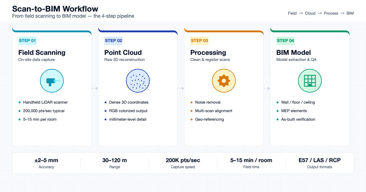
The end-to-end scan-to-BIM workflow has four phases:
- Pre-scan planning: Define LOD requirements, plan scanning routes, verify equipment calibration
- Field scanning: Walk through the building with the handheld scanner, capturing point cloud data
- Point cloud processing: Register scans, clean noise, decimate for performance, align to project coordinate system
- BIM modeling: Import point cloud into Revit (or other BIM software), model building elements, validate against the original point cloud
Each phase feeds into the next, and decisions in one phase affect downstream quality. The most common source of rework is inadequate scanning coverage in phase 2 — a wall section that was missed or captured at poor angle becomes a modeling gap in phase 4 that requires a return site visit.
Choosing the Right Handheld LiDAR Scanner for BIM
Key Specifications to Evaluate
Not all handheld LiDARs perform the same in building interiors. Here are the specs that matter for scan-to-BIM work:
Point rate and density. Higher point rates produce denser clouds, which means better edge definition for modeling walls, pipes, and structural elements. For most interior BIM work, 100,000+ pts/s is the practical minimum. At 200,000 pts/s with a non-repetitive scan pattern, a single pass builds 3–5 million points per second of walking time.
Detection range. Interior BIM rarely needs more than 20–30m range. Anything beyond that is a bonus for large atriums or warehouse spaces. Range at low reflectivity (10% — dark surfaces, black ductwork) is the practical number, not the 90% reflectivity headline spec.
Blind zone. The minimum detection distance determines how close the scanner can get to surfaces without losing data. For interior work, ≤5cm is ideal. A 10cm blind zone means you can't capture tight mechanical room details where pipes run centimeters apart.
Field of view. Vertical FOV determines how much of the environment the scanner captures per pass. A 70° vertical FOV (-10° to +60°) from a 1.5m hold height covers from floor level to roughly 3m above — ceiling tiles, light fixtures, and overhead MEP in most commercial buildings. Narrower FOVs require multiple passes at different angles.
IP rating. Indoor-only scanning can work with IP54. But BIM scans often happen in active construction sites, mechanical rooms with condensation, or building exteriors during feasibility surveys. IP67 eliminates weather and dust from the risk list.
Weight and battery life. A 400g scanner you can hold at arm's length for an hour beats a 1.2kg unit that forces arm rests every 15 minutes. Battery life of 2+ hours covers most single-floor scans without interruption.
Built-in IMU with time sync. The IMU quality and its synchronization with the LiDAR are the single biggest factors affecting SLAM accuracy. Built-in IMU with hardware PTP v2 sync is the gold standard — external IMU modules with software timestamp alignment introduce drift.
Anti-interference. If you're scanning with multiple handheld units simultaneously (large buildings with tight timelines), LiDAR-to-LiDAR interference creates noisy point clouds. Built-in anti-interference eliminates this.
Handheld LiDAR Scanner Comparison for BIM Use Cases
| Specification | Leica BLK2GO | NavVis VLX | Xiaomi / Livox Mid-360 Handheld (e.g., MandEye) | Trimble X7 | iPhone Pro LiDAR | Custom Build (M360-based) |
|---|---|---|---|---|---|---|
| LiDAR type | Multi-beam | Profiling | Non-repetitive solid-state | Panoramic | dToF | Non-repetitive solid-state |
| Point rate | 420,000 pts/s | 100,000 pts/s | 200,000 pts/s | 120,000 pts/s | ~10,000 pts/s | 200,000 pts/s |
| Detection range | 0.3–25m | 0.1–20m | 0.05–50m | 0.3–80m | 0.05–5m | 0.05–50m |
| Blind zone | 30cm | 10cm | 5cm | 5cm | 1cm | 5cm |
| Vertical FOV | 360° (spherical) | 144° | 70° | 300° | ~120° | 70° |
| IP rating | IP54 | IP51 | IP67 (depends on housing) | IP54 | IP68 (phone) | IP67 |
| Weight | 775g | 3.2kg | ~650g | 2.6kg | 240g | ~600g (est.) |
| Battery life | ~45 min | ~2 hours | ~1.5 hours | ~4 hours | All-day | Varies by integration |
| IMU | Built-in | Built-in | Built-in | Built-in | Built-in | Built-in 6-axis + PTP v2 |
| Price range | $35,000–$40,000 | $40,000–$55,000 | $4,000–$6,000 | $30,000–$35,000 | $1,099 (phone) | $2,500–$5,000 (components) |
The "Custom Build" column represents a do-it-yourself approach where you integrate a LiDAR sensor like the Livox M360 into a handheld rig with a compute unit (Jetson Orin Nano or similar) running your preferred SLAM algorithm. The M360's specs — 200,000 pts/s, 5cm blind zone, 70° vertical FOV, IP67, 408g, built-in IMU with PTP v2 — make it a strong candidate for teams that want control over the scanning stack without the price premium of commercial handheld units.
A 2026 MDPI study validated this approach using a MandEye handheld scanner based on the Livox Mid-360 sensor (similar architecture to M360). The SLAM-based mobile system achieved geometric agreement within 10–15mm against a Leica P40 terrestrial reference for cylindrical features and edges, and under 10mm for planar surfaces. That accuracy is sufficient for LOD 200–300 BIM modeling.
When to Build vs Buy a Handheld Scanner
This decision comes down to three factors: budget, in-house technical capability, and workflow control.
Buy a commercial unit when:
- Your team has no robotics or SLAM engineering experience
- You need a turnkey solution with vendor support and training
- Your timeline doesn't allow for development and integration work
- Your organization values warranty, repair services, and standardized outputs
Commercial handheld scanners (Leica BLK2GO, NavVis VLX, Trimble X7) are mature products with polished software workflows. You unbox, calibrate, and scan. When something breaks, you call support.
Build a custom handheld when:
- Budget is constrained — a complete custom build with M360 + Jetson Orin + housing costs $2,500–$5,000 in components vs $35,000–$55,000 for commercial units
- You have in-house ROS/SLAM expertise or are willing to develop it
- You need control over the SLAM algorithm, point cloud format, or integration with existing pipelines
- You're scanning environments where commercial units don't fit (custom form factors, specialized mounting)
- You want to iterate on hardware without vendor lock-in
Building isn't for everyone. A poorly calibrated custom rig will produce SLAM drift that makes the point cloud unusable. But for teams that already run ROS stacks for robotics work or have embedded systems expertise, a custom handheld scanner based on the M360 or similar solid-state LiDAR delivers 80–90% of commercial performance at 10–15% of the cost.
Step-by-Step Scan-to-BIM Workflow
Phase 1 — Pre-Scan Planning
Before walking into the building, define what you're trying to capture. Three decisions drive everything else:
LOD (Level of Development) requirement. This determines scanning density, modeling effort, and total cost:
| LOD Level | Typical Use | What It Means |
|---|---|---|
| LOD 200 | Space planning, lease agreements | Generic geometry — "there's a wall here, approximately this thick" |
| LOD 300 | Construction documents, renovation permits | Accurate geometry with correct dimensions |
| LOD 350 | MEP coordination | LOD 300 + connections, supports, clearances |
| LOD 400 | Fabrication | Manufacturing-level detail — every bolt, weld, splice |
Most renovation and facility management projects need LOD 200–300. LOD 350 for MEP coordination in complex buildings. LOD 400 only when fabricating from the model. Modeling an entire building at LOD 400 when you only need LOD 300 for the renovation scope is a common budget mistake.
Scanning route planning. Walk the building first (or study floor plans if available). Plan your scanning path to avoid gaps:
- Start near an entry point with distinct features (doors, corners) for SLAM initialization
- Maintain 0.5–1.0 m/s walking speed for most handheld systems
- Overlap each room's scan coverage by 20–30% at doorways
- Plan for closed loops — returning to your starting point — so SLAM can close the loop and reduce drift
- Identify featureless zones (long corridors, open warehouse floors) where you may need supplementary scans from different angles
Equipment check. Verify sensor calibration (if your system supports it), charge batteries fully, clear storage on the recording device, and confirm the SLAM software is running the correct configuration for indoor scanning.
Phase 2 — Field Scanning Best Practices
This is where technique matters. The same scanner in different hands produces meaningfully different point cloud quality.
Walking speed and motion. SLAM algorithms assume relatively smooth, human-walking-speed motion. Sudden stops, direction changes, or rapid turning create IMU spikes that degrade localization. Walk at a steady pace. When you need to change direction, slow down first. Avoid running, skipping, or spinning.
Scanner position. Hold the scanner at a consistent height — chest to eye level (1.4–1.7m) works for most interiors. Vary the angle periodically: walk a room holding the scanner slightly forward-tilted to catch floor details, then slightly back-tilted to get ceiling features.
The M360's 70°×360° FOV is particularly useful here. From a 1.5m hold height, the -10° to +60° vertical coverage captures ground-level details (baseboards, floor obstructions), wall surfaces, and ceiling elements (tiles, light fixtures, ductwork) in a single pass. Scanners with narrower FOVs require separate ceiling-only passes or accept incomplete overhead coverage.
Coverage patterns. For each room, plan for two passes if possible — one along the perimeter and one diagonal or cross-pattern. This produces overlap from different angles, filling in shadow zones where a single pass misses surfaces behind furniture, columns, or equipment. The second pass also provides SLAM with more geometric data, reducing drift.
Environmental awareness. Moving objects — people walking through, forklifts operating, doors swinging — create noise in the point cloud (ghost points, duplicated surfaces). Try to scan during low-occupancy periods. If that's not possible, pause briefly at doorways and let people pass before continuing.
Glass and reflective surfaces. LiDAR pulses either pass through or scatter off glass windows, mirrors, and polished metal surfaces. These areas produce either holes in the point cloud (the laser passes through and hits something behind the glass) or noise (scattered returns). Plan to supplement these areas with camera photos or manual measurements.
Phase 3 — Point Cloud Processing
Raw SLAM output isn't ready for BIM modeling. Three processing steps transform it into usable data:
Registration and loop closure. If your scanning route included closed loops, the SLAM algorithm should have performed loop closure — adjusting the trajectory to close the loop and reduce accumulated drift. Verify this visually: check if walls align cleanly at the point where you returned to your starting position. Gaps or offsets indicate missed loop closure, which means manual registration adjustment or a repeat scan.
For multi-floor buildings, align each floor's point cloud to a common coordinate system using known reference points (survey control points, building corners, elevator shafts).
Noise removal. Remove moving-object artifacts (people, equipment), ghost points from reflective surfaces, and outlier noise. Most SLAM software (CloudCompare, HDMapping, Leica Cyclone) has automated outlier removal filters, but manual inspection is still needed for glass zones and complex MEP areas.
Decimation. A dense point cloud from a multi-room scan can exceed 500 million points. Importing this directly into Revit will bring the software to a standstill. Decimate (reduce point density) to 50–100 million points for Revit import while maintaining sufficient detail for modeling. CloudCompare's subsampling tools handle this well.
Export format. For Revit import, use Autodesk ReCap to convert raw point cloud data to .RCP format. ReCap also handles registration, decimation, and coordinate system assignment. If you're using BlenderBIM or FreeCAD (open-source workflows), import the .E57 or .PLY files directly.
Phase 4 — From Point Cloud to BIM Model
Import into BIM software. In Autodesk Revit, link the .RCP point cloud file. Position it using shared coordinates or manual alignment to known reference points. The point cloud appears as a visual backdrop — you can't edit it, but you model against it.
Modeling approach. Two philosophies exist, and the choice matters:
As-built (true geometry): Model walls, floors, and elements exactly as they exist — leaning walls stay leaning, sagging floors stay sagging. Required for heritage documentation, structural analysis, and legal documentation where accuracy to actual conditions is critical.
Design intent (orthogonal): Straighten walls to 90°, level floors, and model elements to their intended dimensions rather than their as-built condition. Standard practice for renovation design — the model represents what you're planning to build, not what currently exists.
Most renovation projects use design intent for the architectural model and as-built for MEP systems, where actual pipe and duct positions matter for coordination.
Modeling workflow in Revit:
- Start with major structural elements (columns, beams, floor slabs) using the point cloud as geometry reference
- Add walls, aligning Revit wall types to point cloud surfaces
- Model openings (doors, windows) using point cloud edge detection
- Add ceiling elements, raised floors, and soffits
- Model MEP systems (ducts, pipes, cable trays) at the required LOD — this is where point cloud density pays off, because distinguishing a 6" pipe from an 8" pipe requires clear surface definition
- Add annotations, dimensions, and parameters per project requirements
Validation. Run dimensional spot-checks by measuring key dimensions in the model against the point cloud. Cloud-to-BIM deviation should stay within your LOD tolerance: typically ±15–25mm for LOD 300, ±10mm for LOD 350.
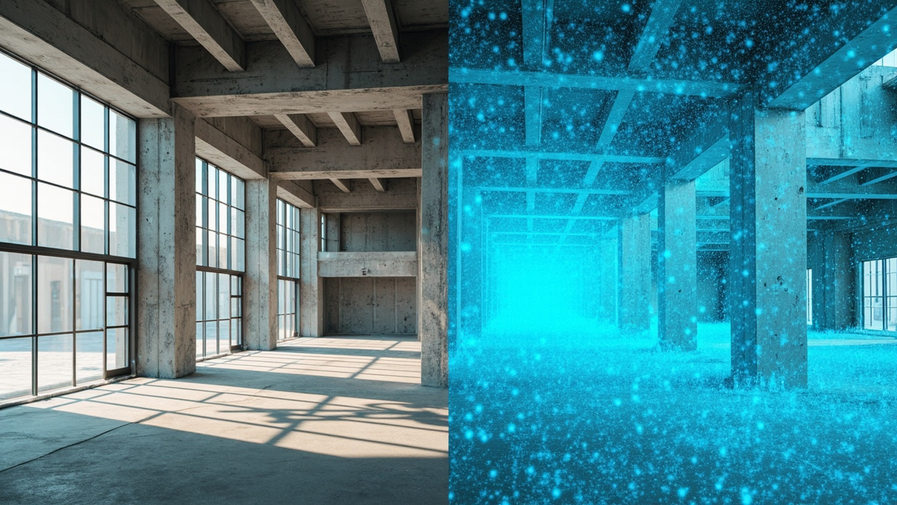
Practical tip: Always deliver the point cloud alongside the Revit model. Downstream users (contractors, subcontractors) often need to reference the original scan data for detail that falls below the BIM model's LOD. A 50GB Revit file with embedded point cloud is painful; a 200MB Revit model linked to a 20GB point cloud works fine.
Accuracy Assessment: How Good Is Your Scan-to-BIM Result?
Accuracy in scan-to-BIM isn't a single number. It's a chain: sensor accuracy × SLAM accuracy × registration accuracy × modeling accuracy. Each stage adds error.
| Stage | Typical accuracy contribution | What affects it |
|---|---|---|
| LiDAR sensor | ±2–5mm (@10m) | Reflectivity, surface angle, range |
| SLAM trajectory | ±5–15mm (local), ±10–30mm (global) | Environmental features, walking speed, loop closure |
| Registration (multi-scan) | ±2–5mm | Control point quality, overlap |
| BIM modeling | ±5–15mm | Element identification, modeling tolerance, as-built vs design intent |
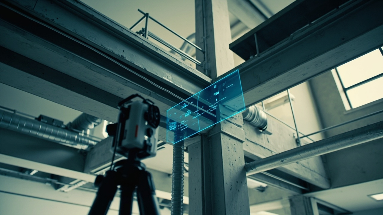
The result: expect ±10–20mm global accuracy for a well-executed handheld scan-to-BIM project at LOD 300. Tighter tolerances (±5mm) are possible with careful SLAM execution and modeling to true as-built geometry, but they significantly increase modeling time.
LOD-to-accuracy mapping
| LOD Level | Modeling tolerance | Point cloud accuracy needed | Suitable applications |
|---|---|---|---|
| LOD 200 | ±25–50mm | ±30mm+ | Space planning, lease layouts |
| LOD 300 | ±10–25mm | ±15mm | Construction documents, permits |
| LOD 350 | ±5–15mm | ±10mm | MEP coordination, clash detection |
| LOD 400 | ±2–5mm | ±5mm | Fabrication, pre-fab spools |
Handheld SLAM scanners comfortably support LOD 200–300 with a single pass. LOD 350 requires careful scanning technique, supplementary terrestrial scans for detail zones, and experienced BIM modelers. LOD 400 is generally outside the capability range of handheld-only workflows — it needs terrestrial scanning or hybrid approaches.
Common Challenges and How to Overcome Them
SLAM drift in long corridors
Long, featureless hallways with repetitive geometry (identical doors, uniform walls) are SLAM's worst enemy. The algorithm loses distinctive features to anchor position estimates, and error accumulates linearly with distance walked.
Solutions:
- Walk down the center of the corridor rather than along one wall — this keeps both walls in view
- Close loops by returning to the starting point, even if it means retracing your path
- Place distinctive objects (brightly colored targets, survey markers) at regular intervals before scanning
- Break long corridors into segments, scanning each as a separate session with explicit loop closures
Glass and reflective surfaces
Glass windows, mirrors, and polished metal surfaces produce holes or noise in the point cloud. No handheld LiDAR scanner handles these reliably.
Workarounds:
- Scan from both sides of the glass — you'll capture the interior surface from one side and the exterior surface from the other
- Supplement with photography for glass areas — cameras capture reflective surfaces that LiDAR can't
- Apply removable matte spray to small metal surfaces during scanning (with permission)
- Document glass zones for the BIM modeler so they know to model from architectural drawings or field measurements rather than the point cloud
Point cloud file size
A single-floor scan of a 20,000 sq ft commercial space can produce 200–500 million points, resulting in a 10–30GB point cloud file. Revit struggles with anything over 100 million linked points.
Management strategies:
- Decimate aggressively for Revit import — 50–80 million points is sufficient for LOD 300 modeling
- Keep the full-resolution point cloud in CloudCompare for reference and detail extraction
- Use Autodesk ReCap's region cropping to split large scans into per-room or per-zone files
- Link rather than embed point clouds in Revit models
Multi-floor alignment
Scanning each floor independently produces accurate per-floor point clouds, but aligning them to a building-wide coordinate system introduces error at floor transitions.
Approach:
- Use known vertical references (elevator shafts, stairwells) scanned on adjacent floors as alignment anchors
- Capture at least one overlap zone between floors (stairwell) during scanning
- Apply a survey control framework with known benchmarks for projects requiring tight vertical accuracy
Getting Started with Handheld LiDAR for BIM
The right entry point depends on your project volume and technical capacity.
For firms scanning occasionally (1–3 projects/year): Rent a commercial handheld unit or hire a scanning service provider. The per-project cost of renting ($500–$1,500/week) plus BIM modeling outsourcing ($0.40–$3.00/sq ft) beats purchasing hardware that sits idle between projects.
For firms scanning regularly (10+ projects/year): Purchase a commercial handheld system. The ROI typically materializes within 6–12 projects through reduced scanning time, eliminated return visits, and in-house quality control. Budget $35,000–$45,000 for hardware plus $2,000–$4,000/year for software subscriptions.
For budget-sensitive teams with technical capability: A custom handheld build based on the M360 (408g, 200kHz, IP67, 70°×360° FOV, built-in IMU with PTP v2) offers the most flexible cost structure. At $2,500–$5,000 in components plus your existing compute platform and SLAM development effort, it's the lowest-cost entry into professional-grade handheld scanning. Teams already running ROS-based robotic systems or embedded Linux platforms can often integrate a handheld scanning mode with minimal additional investment.
The industry is moving toward handheld and mobile scanning as the default for interior reality capture. Terrestrial scanners will still handle detail zones and high-accuracy requirements, but the majority of scan-to-BIM field time is shifting to handheld systems. AI-assisted point cloud segmentation and automated BIM element recognition are the next frontier — several research groups (Scan2BIM-NET, A-Scan2BIM) are already demonstrating deep learning approaches that automatically classify walls, pipes, and structural elements from point clouds, cutting modeling time by 30–50%.
For now, the workflow is still fundamentally manual — you scan, you process, you model. But the hardware is cheaper, the software is more accessible, and the accuracy is good enough for most real-world BIM work. The barrier to entry has never been lower.
If you're evaluating handheld LiDAR options for scan-to-BIM projects, contact SmartBotParts — we can share benchmark data on M360-based builds or help with component selection.
© 2026 SmartBotParts. All rights reserved.
Handheld scanner specifications and pricing are based on publicly available manufacturer data as of mid-2026. Accuracy benchmarks reference the MDPI 2026 study (doi:10.3390/infrastructures6010024) and SmartBotParts internal testing. Actual performance varies with environment, operator technique, and SLAM configuration. Always validate with evaluation units before committing to fleet deployment.
Frequently Asked Questions
What accuracy can I expect from a handheld LiDAR scanner for BIM?
For a well-executed scan-to-BIM workflow using a handheld SLAM scanner, expect ±10–20mm global accuracy at LOD 300 — the standard for construction documents and renovation permits. Local accuracy (within a single room or small area) is typically tighter at ±5–10mm. These numbers assume proper loop closure, reasonable walking speed, and an experienced operator. Without loop closure or in featureless environments, global accuracy can degrade to ±30mm or worse. The MDPI 2026 study validated ±10–15mm accuracy for a Livox-based handheld system against a terrestrial reference.
How long does it take to scan a building with a handheld LiDAR?
As a rough guide, a single operator with a handheld scanner covers 1,000–2,000 sq ft per hour of interior floor space at walking speed. A 50,000 sq ft commercial building typically takes 4–8 hours of scanning time. Add 30–50% for complex mechanical rooms, multi-level spaces, and areas with limited access. Post-processing (registration, cleaning, decimation) adds 4–8 hours for a building that size. BIM modeling is the longest phase — 1–3 weeks for a 50,000 sq ft building at LOD 300, depending on MEP density.
Can I use a handheld LiDAR scanner for outdoor BIM projects?
Yes, with caveats. Handheld scanners with IP67 protection (like M360-based builds) handle rain, dust, and outdoor conditions. But outdoor environments create SLAM challenges: fewer geometric features for localization, GPS-denied areas (urban canyons, under tree cover), and larger scanning areas that amplify drift. For outdoor building facades, combine handheld scanning for detail areas with UAV photogrammetry or terrestrial scanning for the overall building envelope. For outdoor site surveys (topography, landscaping), terrestrial or UAV-based LiDAR is more appropriate than handheld.
What software do I need for scan-to-BIM?
The minimum software stack: a SLAM processing tool (CloudCompare, HDMapping, or the vendor's proprietary software) for point cloud processing, Autodesk ReCap for registration and format conversion, and a BIM modeling platform (Autodesk Revit is the industry standard). Optional but useful: Navisworks for clash detection, Trimble RealWorks for advanced registration, and BlenderBIM or FreeCAD for open-source workflows. The MDPI 2026 study demonstrated a complete open-source pipeline using COLMAP for photogrammetry, CloudCompare for processing, and BlenderBIM for modeling — viable for budget-constrained projects.
How much does a handheld LiDAR scanner cost?
Commercial handheld LiDAR scanners for BIM work range from $4,000 (entry-level, LiDAR sensor-based units like MandEye) to $55,000 (premium units like NavVis VLX). The mid-range sweet spot for most AEC firms is $30,000–$40,000 (Leica BLK2GO, Trimble X7). Custom-built handheld scanners using solid-state LiDAR sensors like the Livox M360 can be assembled for $2,500–$5,000 in components, but this requires in-house SLAM and robotics expertise. Software costs add $2,000–$8,000 annually (Autodesk ReCap + Revit subscription). Total first-year investment for a commercial handheld system with software: $35,000–$60,000.